Panels
Element panel
The element panel is what the column on the right shows under the outliner while one building element is selected, a wall, a door or a window, a room, a column, a beam, a pipe, a device or a sanitary appliance: its reference, its IFC class, then its sections, from its assembly and its own fields to its patterns and its reference. What you set there is written into the element's entry in the contract, and the model is built again at once.
What it is
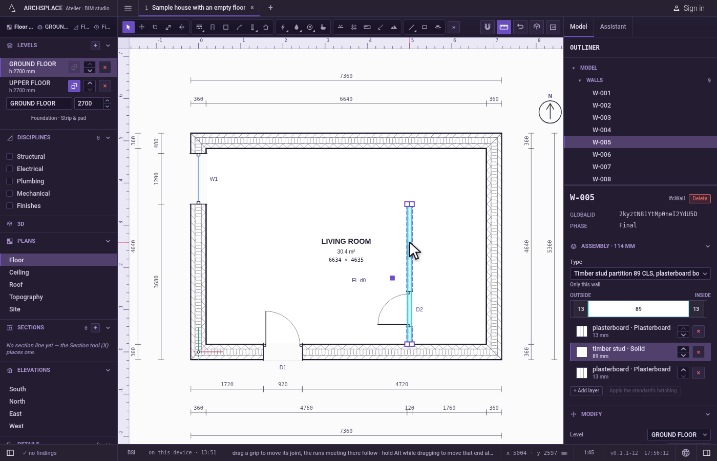
The element panel stands under the outliner, in the column on the right, while one building element is selected. Its head shows the element's reference, such as W-005, the IFC class it is exported as, such as IfcWall, and Delete. While faces and edges of free geometry are selected, the head reads SELECTION and counts them instead. Under the head a short table gives the element's GlobalId, its Phase and, for some elements, what they are, such as the family and the size of a door.
Then come its sections, as far as the element has them, each folding under its title:
- Assembly, first for a wall, its title giving the total thickness: the wall's Type, how many walls share it, and its layers from Outside to Inside. Its own page tells it all.
- Foundation, folded at first, for a wall or a column standing on a footing: one line names the footing, such as FT-005, its kind and whether it is derived or explicit, and says to pick it on the ground level's structural plan. When that footing was omitted, the line says so, with Restore footing.
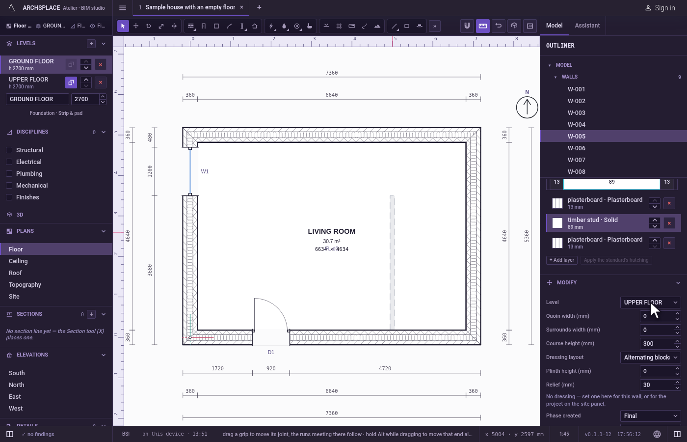
- Modify, open: the element's own fields. A wall has its Level; its dressing stone, the Quoin width, the Surrounds width, the Course height, the layout (alternate, uniform or band), the Plinth height and the relief; Phase created and Demolished in, when the project has more than one plain phase; and its Length. A door or a window has its family, its mark, its size and sill, its position on the wall, its frame and its sashes, and the way it hinges and swings; a room its name, its use and its ceiling height; a column its width, depth, rotation and position; a beam its length, width and depth; a pipe its system, diameter and fall; a device its mounting height.
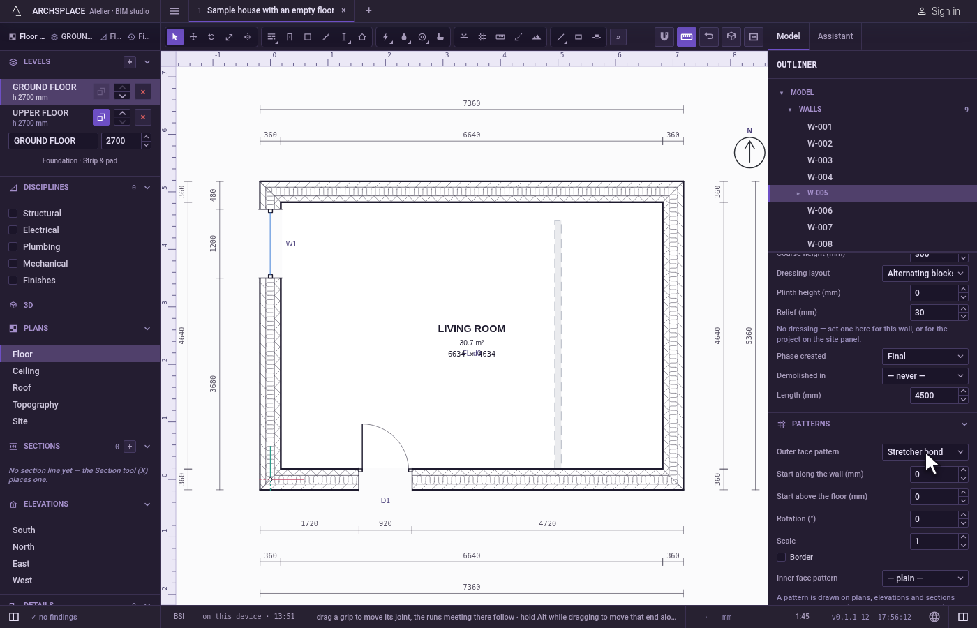
- Patterns, folded at first, for a wall or a room: a wall's Outer face pattern and Inner face pattern, a room's Floor pattern and Ceiling pattern with Add floor area and Add ceiling area, and Patterns…, which opens the list of the project's patterns. A line reminds that patterns are drawn when Finishes is on.
- Group into component, a button, when the element can become a component.
- Circuits, Plumbing, Ventilation or Air conditioning, for a device of an installation.
- Interior elevations, for a room.
- Associated reference, folded at first: a free field for a code such as an NBS reference, a SKU or a supplier link.
The panel keeps each section open or folded as you last left it.
When to use it
- Changing the type, the build-up or the length of a wall.
- Setting the size of a door or a window, or the name and use of a room.
- Moving an element to another level, or setting the phase it is built or demolished in.
- Laying a pattern on a wall's face, or on a room's floor or ceiling.
- Giving an element a supplier's code.
The steps
Select a wall. With the Select tool, click a wall. The panel shows W-005, IfcWall and Delete at its head, then its table, Assembly, Modify and the sections that follow.
Change its level. In Modify, choose another level in Level. The wall moves to that level's plan.
Set its length. In Length, type 4500 and press
Enter. The wall's start stays where it is and its end moves along its line.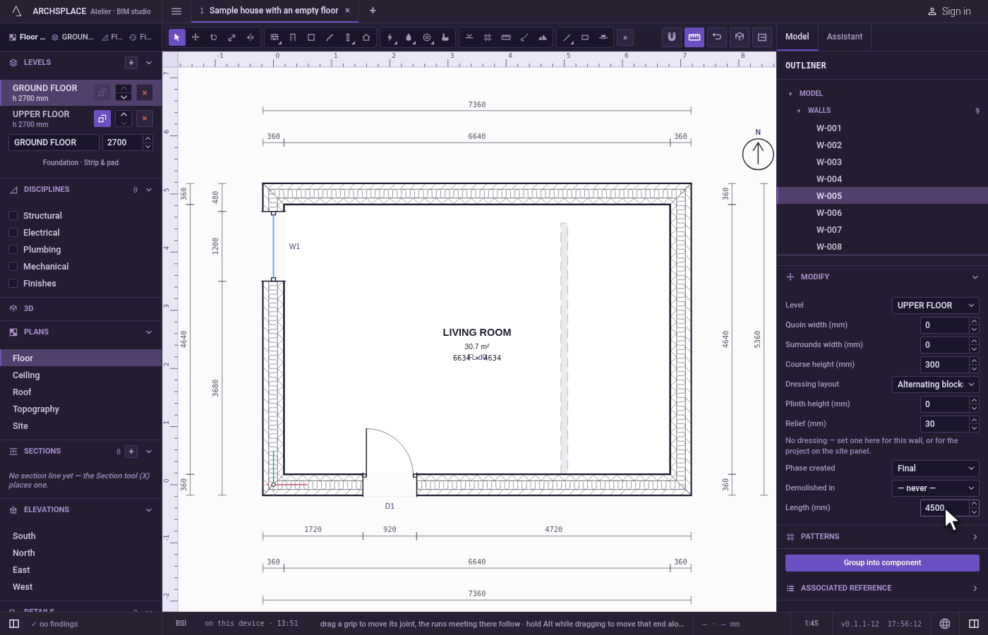
Lay a pattern on its outer face. Open Patterns and choose a pattern in Outer face pattern. With Finishes on, the elevations draw it on the wall.
Write its reference. Open Associated reference, type a supplier's code and press
Enter.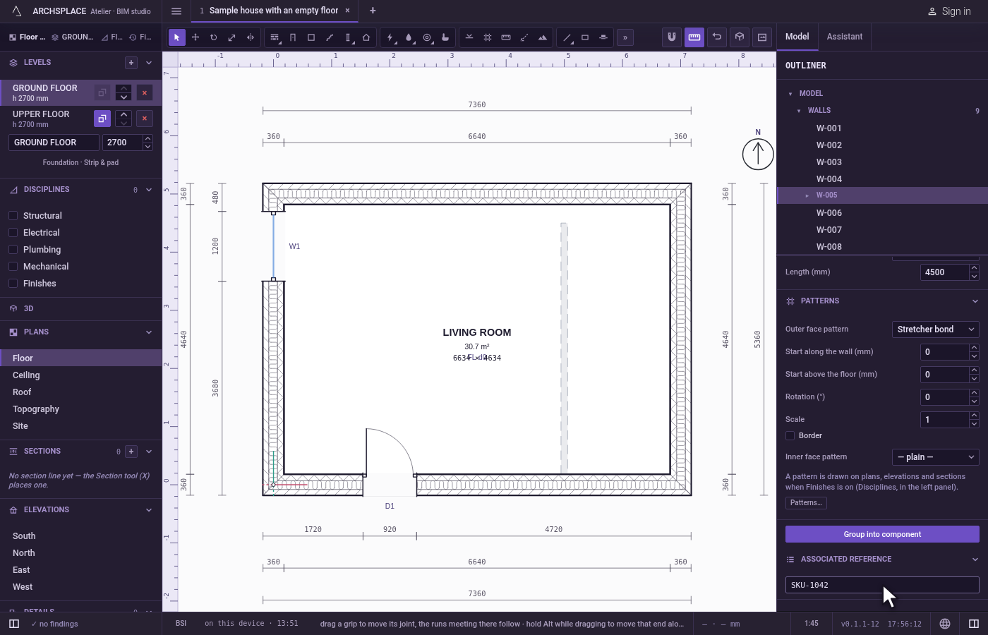
What it refuses
- A number out of a field's range. The field goes back to the value that holds and says why under it, such as the least length a wall can have.
- A field left with no number. It says that a number is needed, and the value stays.
- Phase fields in a project of one plain phase. They are not shown: there is nothing to choose.
What it writes to the contract
Each change rewrites the element's entry in place, in its list of the contract, such as walls for a wall, as one step that one Ctrl+Z takes back. For a wall, Level writes level, the dressing dressing with only the values you changed, Phase created phase, Demolished in demolished, Length a new end along the wall, the patterns facadePattern and liningPattern, and Associated reference reference. The other elements write the keys of their own fields the same way, such as floorPattern and ceilingPattern for a room. What the model works out, the thickness, the footing and the GlobalId, is never written.
Common questions
How do I change the type of a wall?
Select the wall and choose another type in Type, at the top of its Assembly section. The wall takes that type's layers and thickness at once.
How do I put a stone pattern on one wall's outer face?
Select the wall, open Patterns in its panel and choose the pattern in Outer face pattern. Patterns are drawn when Finishes is on, in Disciplines in the left panel.
Why is there no Phase created field?
Because the project has only one plain phase. Phase created and Demolished in show as soon as there are two.
How do I give an element a supplier code?
Open Associated reference, the last section of its panel, and type a code such as an NBS reference, a SKU or a supplier link.