Views
Sections and elevations
A section is the building cut by a vertical plane: every wall, floor and footing the plane crosses is drawn cut, with the hatch of each of its layers, and everything beyond the plane is drawn in projection. An elevation is the building seen square from one side, north, south, east or west, with the ground in front of it and the roofs that hide its walls.
What it is
Sections and elevations are drawings the studio works out from the model. You never draw them line by line: each time the model changes, the section or the elevation is drawn again from it, so a wall you move on the plan moves in every section at once.
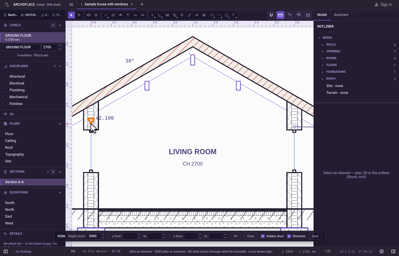
A section starts from a cut line on the plan. Every wall the vertical plane crosses is cut exactly where the plane passes through its footprint, at the angle the wall stands at, and its layers are drawn side by side, each one with the hatch its template gives that material. Floors are cut along their real outline at that depth, so an L-shaped floor cut through one arm is as wide as that arm. Footings are cut as their layers too, and the ground the plane crosses is a cut profile under everything, hatched as earth or rock. Beyond the plane, the faces the eye stands in front of are drawn in projection and shaded like an elevation: the outside of the building where the plane lies outside it, the lining of the rooms where it looks into them, the deeper faces painted first so that nothing shows through what stands in front of it.
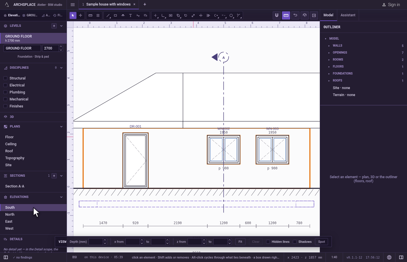
An elevation is the building seen square from one side. The four elevations, north, south, east and west, always exist. Each one draws the faces that look its way, as wide as the plan's outer skin, cuts away whatever a roof in front of a wall hides, and draws the near ground over the facade below ground level with the far ground behind the building.
Both kinds of drawing are dimensioned the way the plans are. Under the drawing, chains give the openings and the piers, the walls face to face and the overall width. On the right, every level's datum, the floors, the roofs' seats and crowns and the overall height. A section also gives the sills and heads of the openings it cuts. The grid axes square to the view stand through the drawing with their bubble above it, other sections crossing the view are drawn as their dash-dot line with their letter, and the drawing names the openings, the rooms it cuts and the levels at their datums.
When to use it
- Checking how walls, floors, roof and ground meet, with every layer of every wall in sight.
- Showing a facade to a client, with its openings, its roofs and the ground in front of it.
- Preparing the sections and elevations of a set of drawings, cropped to what each sheet needs.
The steps
Place a cut line on the plan. On the floor plan, press
Xor click Section in the toolbar. In the list beside the tools, choose how the cut runs and which way it looks, such as Vertical · looks east (viewer west). Click across the building where the cut should pass. The cut line is drawn with its letter: A for the first section, B for the next.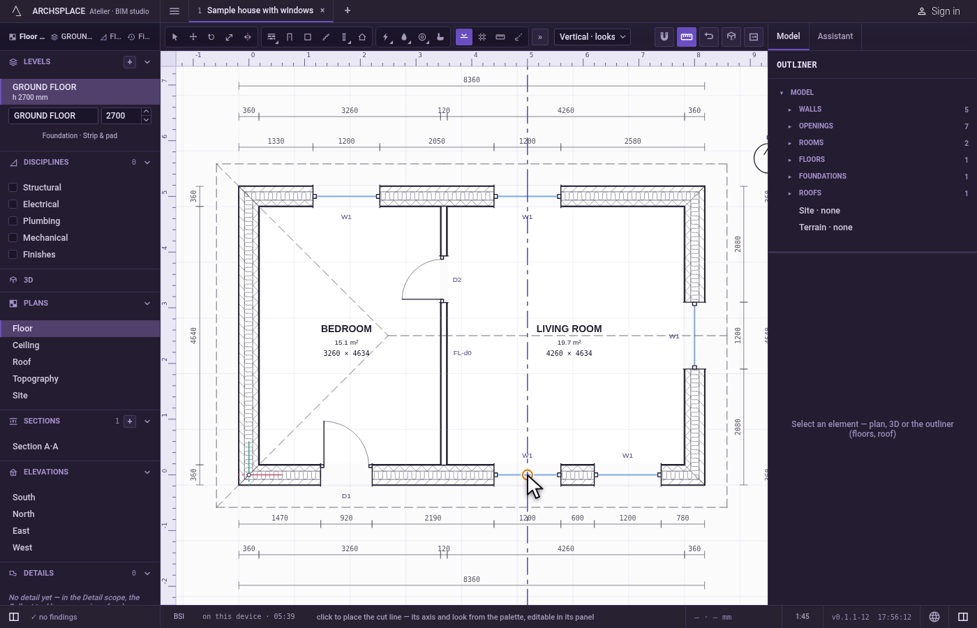
Open the section. In the sidebar, under Sections, click Section A·A. With the cut line selected, the panel on the right also offers Open section view. The drawing fills the screen, and the toolbar now holds Select, Move, Dimension, Grid and the detail tools.
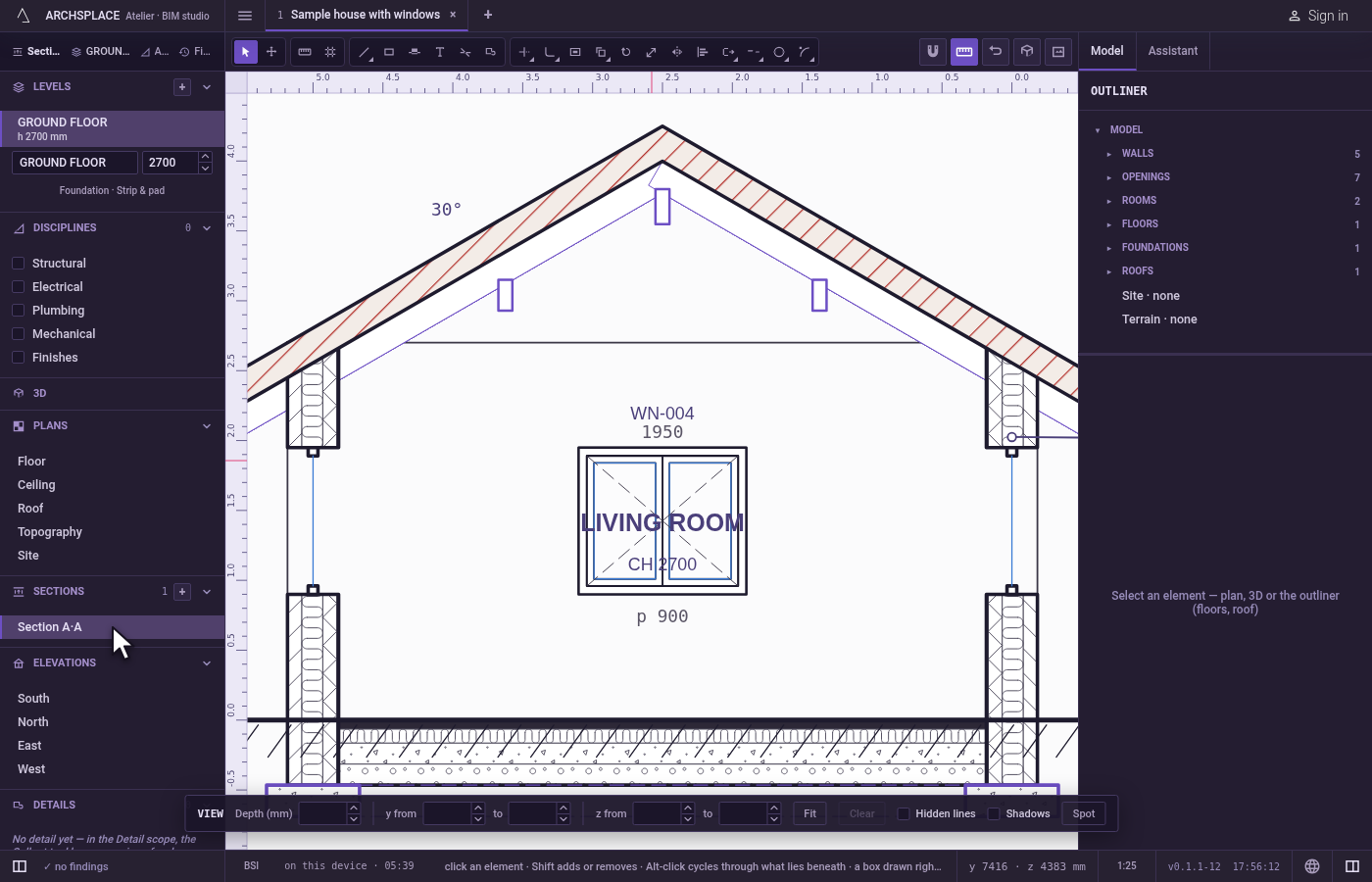
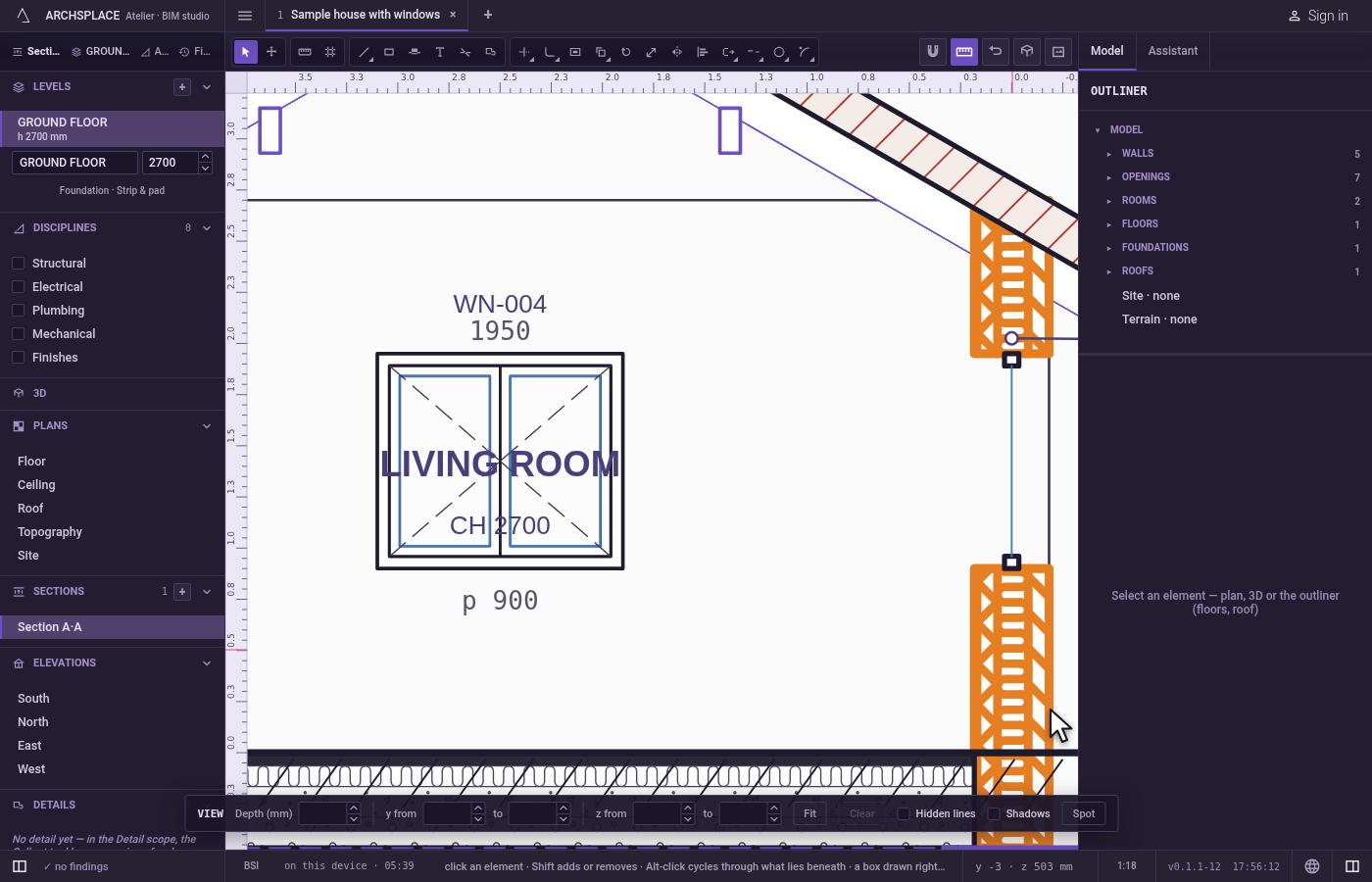
Read the cut. The walls the plane crosses are drawn cut, each layer hatched on its own, and the faces beyond the plane are drawn in projection behind them. Turn the mouse wheel to zoom about the pointer, drag with the middle button to pan, and double-click the middle button to frame the whole drawing again.
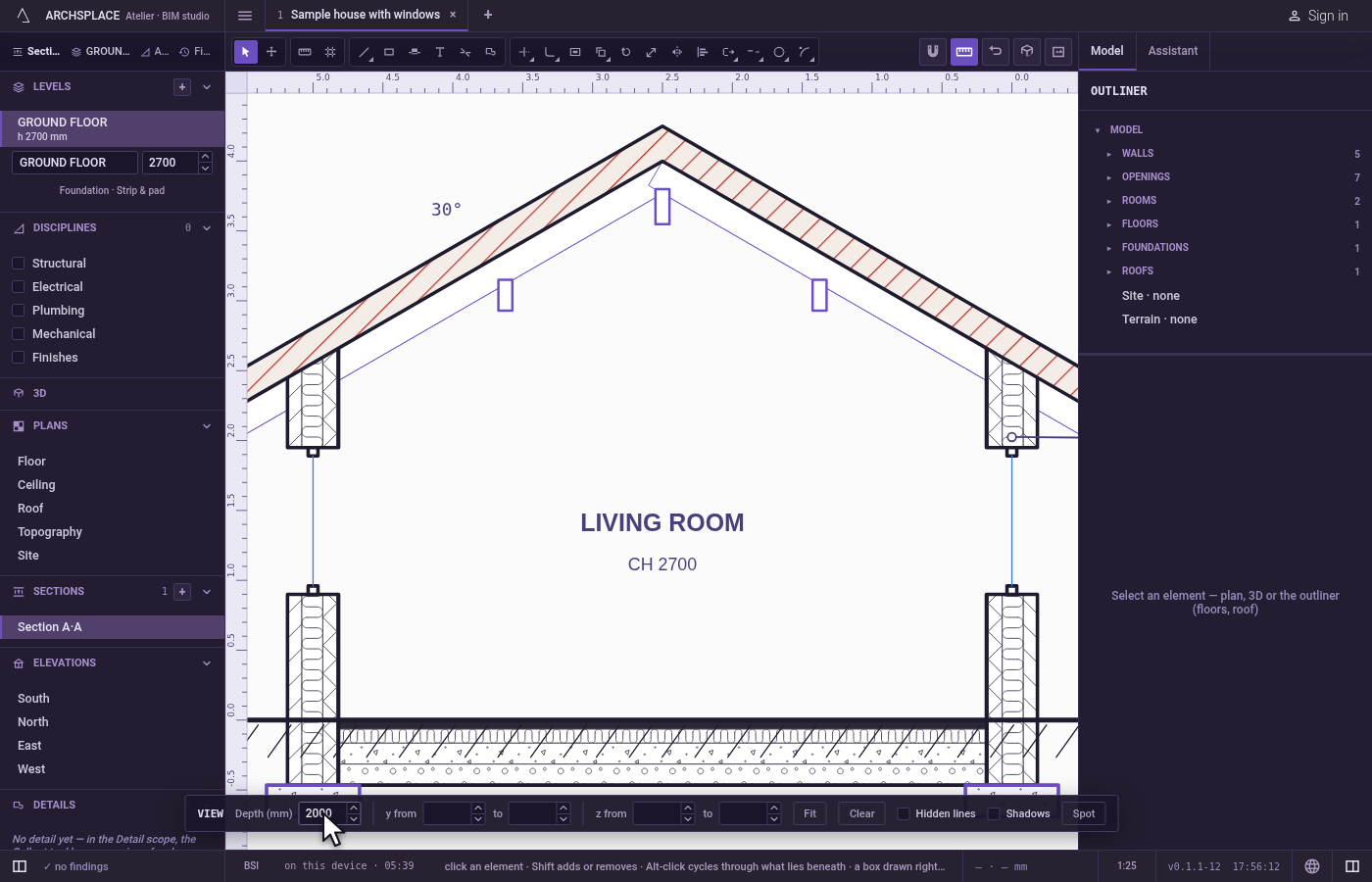
Crop the view. The VIEW strip at the foot of the drawing holds the crop. Type a length in Depth to keep only what stands within that distance behind the cut. x from and to (y from on a view that runs along y) hold the stretch along the cut line, and z from and to hold a band of heights. Fit fills the fields from what the view shows, so you can tighten them, and Clear brings the whole building back.
Choose what it shows. Tick Hidden lines to draw the floors and the walls behind the facade as dashed lines. Tick Shadows to cast the shadows of the eaves and of the window reveals, from a light at the upper left at 45 degrees. Spot, then a click on the drawing, marks the height of that point.
Open an elevation. In the sidebar, under Elevations, click South. The building is drawn as seen from the south, with the same strip at its foot, cropped and shown its own way: every elevation and every section keeps its own crop.
What it refuses
- Drawing on the derived lines. The walls, floors and roofs in a section are the model's. What you add there is annotation: dimensions, grid axes and details. To change a wall, change the model.
- A range with its ends the wrong way round. In the crop, a from that is not smaller than its to is not taken. Emptying one end of a range drops the whole range.
- Anything that is not a number. A crop field keeps its value when what you type is not a number. An empty Depth means no limit.
- A crop that makes no sense. A crop that leaves nothing coherent is not quietly corrected: the model reports it as a finding.
- A section parallel to this one. Only the sections that cross the view are drawn on it; a parallel section draws nothing there.
- Tools with no project open. With no project open, the status bar asks you to open or create one, and the tools do nothing.
What it writes to the contract
The drawing itself is never written: it is worked out from the model each time it is shown. What the contract keeps is where each section stands and how each view is cropped.
The Section tool appends one entry to the contract's stations list: its axis, where it stands in metres, its letter and which way it looks.
The crop and the view's choices are written on that same entry: depth, span (two values along the cut line), heights (two absolute heights), hidden: true, shadows: true, and spots, each a point [u, z] along the cut line and up. An elevation keeps the same keys under elevations, by its side: { "elevations": { "S": { "depth": 6, "hidden": true } } }. An elevation with nothing of its own is not written at all, and Clear removes depth, span and heights.
Related
Common questions
How do I make a section of my building?
On the plan, press X, choose which way the cut looks in the list beside the tools, and click where the cut line should pass. The section is listed under Sections in the sidebar as Section A·A. Click it to open the drawing.
Why are the walls in my section drawn with several hatches?
A wall the plane crosses is cut through every layer of its assembly, and each layer is drawn as its own band with the hatch its template gives that material. A layer with no hatch of its own is filled solid.
Can I show only part of the building in a section?
Yes. The VIEW strip at the foot of the drawing takes a depth behind the cut, a stretch along the cut line and a band of heights. Fit fills them from what the view shows, and Clear brings back the whole building.